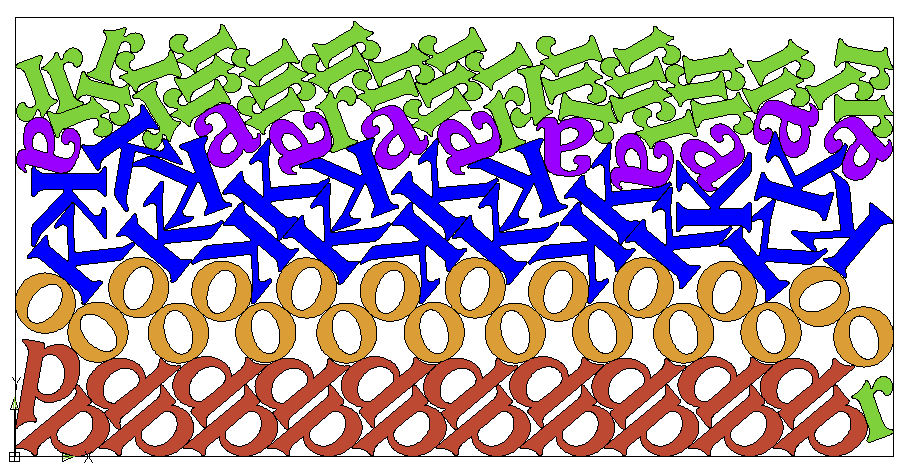
Nesting pattern created by NestProfessor
The example above was chosen because it demonstrates familiar shapes arranged in an unfamiliar configuration. Now imagine software capable of taking virtually any collection of outline shapes, automatically rotating and positioning them to maximize the number of parts that can be cut from a sheet of material.
It quickly becomes clear that this is a task best handled by a computer rather than manually. Nesting optimization requires substantial computational processing to evaluate countless layout possibilities and identify the most efficient arrangement.
Typically, nesting software imports CAD files containing the profiles of the parts to be cut. Because nesting operates in two dimensions, standard file formats such as DXF files are commonly used.
After importing the part outlines, the operator provides additional information, including:
Part spacing requirements vary depending on the cutting method being used, such as routing, plasma cutting, laser cutting, or waterjet cutting.
Once the required information has been entered, the nesting software begins searching for increasingly efficient layouts. As improved solutions are found, the software updates the nesting arrangement and displays key performance metrics such as:
Utilization is one of the most important measurements in nesting. It represents how much of the material sheet is converted into usable parts versus wasted scrap. Higher utilization directly reduces material costs and improves overall production efficiency.
Advanced nesting systems use a variety of optimization techniques to maximize utilization, including:
The longer the nesting engine is allowed to process, the more optimized the layout generally becomes. Eventually, however, the improvements reach a point of diminishing returns, and production requirements typically dictate moving forward with the cut.
At that stage, the nesting software exports a finalized CAD file containing the optimized layout. That file can then be imported into a CAM system to generate toolpaths for CNC routers, plasma tables, waterjets, or laser cutting systems.
— Queen Elizabeth II —